
Blog
Wheel Hardware: Lug Fasteners, Seat Profiles & Assembly Safety

Chapter 3: Wheel Hardware Engineering — Lug Fasteners, Seat Profiles & Assembly Safety
In aftermarket wheel procurement and tire servicing, wheel hardware is frequently overlooked as an inexpensive accessory. However, it represents the sole mechanical interface that secures the rotating wheel assembly to the vehicle chassis.
Even if the PCD, ET, and Center Bore are perfectly matched, using an incompatible lug seat profile or incorrect torque specifications will cause fasteners to back out or shear under dynamic load. This guide details lug bolts vs. nuts, critical seat interfaces, thread specifications, and proper assembly procedures.
1. Fastening Systems: Lug Bolts vs. Lug Nuts
Modern passenger car platforms rely on two primary wheel fastening configurations:
1.1 Lug Bolt System (Wheel Bolts)
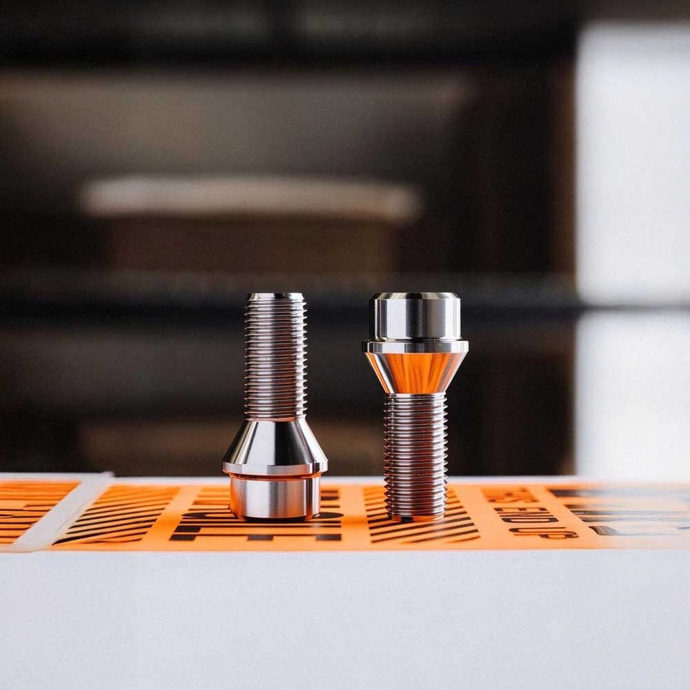
- Architecture: A one-piece fastener combining an integrated hex head, seating shoulder, and threaded shank.
- Mounting Mechanism: The wheel hub flange contains pre-tapped female threads. The wheel is positioned over the hub pilot, and bolts are threaded through the wheel directly into the hub.
- Primary Applications: Predominantly utilized by European manufacturers (Porsche, Mercedes-Benz, BMW, Audi, Volkswagen, Volvo).
- Pros & Cons: Clean hub design simplifies brake service; however, mounting heavy wheel assemblies requires manually balancing the wheel while threading the first bolt. Stripping hub threads necessitates rotor/hub replacement.
1.2 Lug Nut & Wheel Stud System
- Architecture: High-tensile threaded studs are press-fitted into the wheel hub assembly from behind, protruding outward to receive female lug nuts.
- Primary Applications: Standard across Japanese OEMs (Toyota, Honda, Nissan, Subaru), American trucks/muscle cars (Ford, GM, Stellantis), and Korean platforms.
- Pros & Cons: Allows technicians to easily hang the wheel on the protruding studs during installation. Stripped threads only require replacing an individual press-in stud. However, fitting wheel spacers often requires labor-intensive extended stud installations.
2. The Critical Contact Interface: Comparing Lug Seat Profiles
Warning: Fastener seat geometry must match the wheel lug pocket profile identically. Never mix seat profiles!
2.1 60° Conical Seat (Cone / Taper Seat)
- Profile: Features a straight, angled 60-degree taper leading to the shank.
- Industry Standard: The universal standard across more than 95% of aftermarket forged and cast alloy wheels worldwide.
- Mechanical Function: Provides uniform wedge-style surface contact against the wheel pocket, ensuring concentric centering and reliable clamping retention.
2.2 Ball Seat (Radius Seat)
- Profile: Features a curved, spherical radius profile, specified as R12, R13, or R14 (radius in millimeters).
- OEM Standards: Factory-standard on European platforms (VW/Audi typically utilize R13; Mercedes-Benz and Porsche utilize R14).
- Danger of Mismatching: Installing an OEM ball-seat bolt into an aftermarket 60° conical wheel pocket creates a razor-thin line contact instead of full surface distribution. Dynamic shock loads cause severe localized stress, pocket wall galling, and rapid hardware loosening.
2.3 Flat Seat (Mag / Shank Seat)
- Profile: Features an extended cylindrical shank that enters the lug hole, clamped down via an integrated flat captive washer.
- OEM Standards: Found extensively on OEM Toyota, Lexus, and vintage Nissan factory alloy wheels. Aftermarket custom wheels rarely use this design.
3. Thread Specifications & Pitch Identification
Fastener thread sizes are specified using metric designations: Thread Diameter × Thread Pitch (e.g., M14 × 1.5).
| Thread Size & Pitch | Nominal Shank Diameter | Axial Distance Per Thread Turn | Representative OEM Vehicle Applications |
|---|---|---|---|
| M12 × 1.25 | 12 mm | 1.25 mm | Nissan, Subaru, Suzuki, Infiniti |
| M12 × 1.50 | 12 mm | 1.50 mm | Toyota, Honda, Mazda, Hyundai, Kia, BMW (E-chassis) |
| M14 × 1.25 | 14 mm | 1.25 mm | Modern BMW (F & G chassis), MINI |
| M14 × 1.50 | 14 mm | 1.50 mm | Audi, VW, Mercedes-Benz, Porsche, Tesla (Model 3/Y/S/X), Mustang |
| 1/2-20 UNF | 1/2 Inch (12.7 mm) | 20 Threads Per Inch | Classic American Muscle, Jeep Wrangler (JK), Ford (Vintage) |
4. Minimum Thread Engagement Standards
When installing aftermarket wheels or slip-on wheel spacers, verify that the fastener achieves sufficient thread engagement to withstand shear and tensile loads.
Minimum Full Rotations Required:
- M12 × 1.25: Minimum 8.0 full turns
- M12 × 1.50: Minimum 6.5 full turns
- M14 × 1.25: Minimum 9.0 full turns
- M14 × 1.50: Minimum 7.5 full turns
Rule of Thumb: Total thread engagement length must equal or exceed the nominal diameter of the fastener stud (e.g., an M14 bolt requires at least 14 mm of active thread contact within the hub).
5. Installation Protocol: Star Pattern Sequence & Torque Specs
Pneumatic impact guns should never be used for final torque seating. Uneven tightening causes warped brake rotors, cracked mounting pads, and broken studs.
5.1 Cross-Star Tightening Sequence
Always tighten fasteners progressively in a crisscross sequence to center the wheel evenly against the rotor face:
- 4-Lug Pattern: 1 → 3 → 2 → 4 (Cross shape)
- 5-Lug Pattern: 1 → 3 → 5 → 2 → 4 (Star shape)
- 6-Lug Pattern: 1 → 4 → 2 → 5 → 3 → 6 (Opposing alternating pattern)
5.2 Standard Torque Specifications
Always apply final clamping load using a calibrated manual torque wrench:
- M12 Fastener Systems: 110 N·m to 125 N·m (approx. 80 – 90 lb-ft)
- M14 Fastener Systems: 140 N·m to 160 N·m (approx. 105 – 120 lb-ft)
- Heavy-Duty Trucks / 8-Lug Platforms: 175 N·m to 200 N·m (approx. 130 – 150 lb-ft)