

Blog
Wheel Clearance Engineering: Brake Caliper X-Factor, Suspension Gaps & Fender Alignment

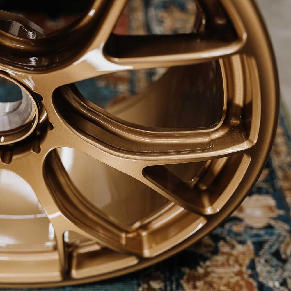
A common pitfall in aftermarket wheel procurement is discovering that a wheel matches nominal PCD, Center Bore, and Offset specs, yet locks solidly against the brake calipers upon installation.
Diameter, width, and offset only describe the wheel's 2D envelope. When dealing with modern multi-piston Big Brake Kits (BBK), inboard suspension struts, and outer fender sheet metal, three-dimensional clearance analysis becomes critical. This guide breaks down the X-Factor, brake profiling templates, inboard suspension gaps, and scrub radius dynamics.
1. The Critical Dimension for Caliper Clearance: What is X-Factor?
In wheel engineering and CNC machining, X-Factor refers specifically to the three-dimensional clearance between the wheel hub mounting pad and the rear contours of the spokes.
1.1 Geometric Definition & Disk Types
- Datum Plane: The machined hub mounting surface mating directly against the brake rotor hat.
- Measurement: The axial distance from this mounting pad out to the innermost profile of the wheel spokes.
- Disk Height Classifications:
- Low Disk (Low X-Factor, < 25 mm): Designed for deep-dish or extreme stepped-lip wheels. Spokes sit close to the hub pad, clearing only standard single-piston sliding calipers. Incompatible with performance big brakes.
- Medium / Standard Disk (Standard X-Factor, 25 mm – 40 mm): Accommodates factory multi-piston setups found on performance trims (e.g., BMW M Sport, Audi S-Line 4-piston brakes).
- High Disk (High X-Factor, > 45 mm): Engineered specifically for oversized aftermarket 6-piston and 8-piston calipers (e.g., Brembo GT, AP Racing Pro 5000R, carbon-ceramic rotors). The spoke base arches aggressively outward to maximize caliper clearance.
2. Utilizing Brake Caliper Profile Templates
Before initiating custom monoblock forged wheel programming, technical procurement should require a verified 1:1 brake profile template rather than relying on vehicle year/make/model alone.
2.1 The Three Envelope Axes
- Axis A (Radial Height): Distance from the axle hub center to the outermost radial peak of the caliper. Verifies that the barrel drop-center does not contact the caliper top edge.
- Axis B (Axial Protrusion): Distance from the rotor hat face outward to the furthest protruding point of the caliper face. Directly dictates minimum spoke clearance.
- Axis C (Inboard Width): Distance from the hub mounting pad inward toward suspension links.
2.2 Minimum Safety Tolerances
- Spoke Back to Caliper Face: Minimum static clearance must be ≥ 3.0 mm (4.0 mm – 5.0 mm recommended to account for wheel flex under heavy cornering).
- Inner Barrel to Caliper Crown: Minimum radial gap must be ≥ 4.0 mm (prevents road debris from lodging between caliper and barrel).
3. Inboard Suspension Clearance
Widening a wheel distributes width both outward toward the body and inward toward chassis struts, sway bar end links, and steering knuckles.
Inner Clearance Change Formula:
Inner Extension = ((New Width - Old Width) × 25.4 / 2) + (New ET - Old ET)
(A positive result indicates the inner rim edge extends closer to the suspension assembly by that value in millimeters).
Safety Threshold: Always maintain a minimum static gap of 8.0 mm to 10.0 mm between the inner rim lip/tire sidewall and suspension components.
4. Outboard Fender Flushness & Scrubbing
Flush fitment aligns the outer wheel edge with the vertical plane of the vehicle's fender arch.
Outer Extension (Poke) Formula:
Outer Extension = ((New Width - Old Width) × 25.4 / 2) - (New ET - Old ET)
- Fender Scrubbing: If outer extension exceeds fender boundaries, suspension compression will force the metal fender lip into the tire shoulder, risking tire sidewall slicing and body damage.
- Mitigation Methods: Adjusting negative camber via adjustable control arms or executing fender rolling (flattening the inner metal lip) provides crucial millimeter clearance.
5. Suspension Geometry: Understanding Scrub Radius
Aggressive offset reductions alter the vehicle's Scrub Radius—the distance at the ground contact patch between the tire centerline and the steering axis (kingpin) projection.
| Scrub Classification | Geometric Alignment | Handling & Safety Implications |
|---|---|---|
| Positive Scrub | Tire contact center sits outboard of the steering axis projection. | Common in RWD and trucks. Enhances road feedback, but excessive positive scrub from low ET wheels creates severe tramlining and kickback over bumps. |
| Negative Scrub | Tire contact center sits inboard of the steering axis projection. | Standard in modern FWD and AWD passenger cars. Promotes dynamic self-centering stability during split-traction braking (e.g., hitting puddles). |
| Zero Scrub | Tire centerline aligns directly over the steering axis point. | Light steering feel at low speeds, but diminishes tactile slip-angle communication near grip limits. |