
Blog
Wheel Anatomy: The Structural Engineering of an Automotive Wheel

An In-Depth Engineering Analysis of Wheel Components and Technical Terminology
In the automotive aftermarket and B2B custom wheel procurement, mastering precise engineering terminology is essential. It is not only the prerequisite for reading 2D and 3D CAD blueprints accurately, but also the key to eliminating tooling errors and spec mismatches during cross-border technical communications.
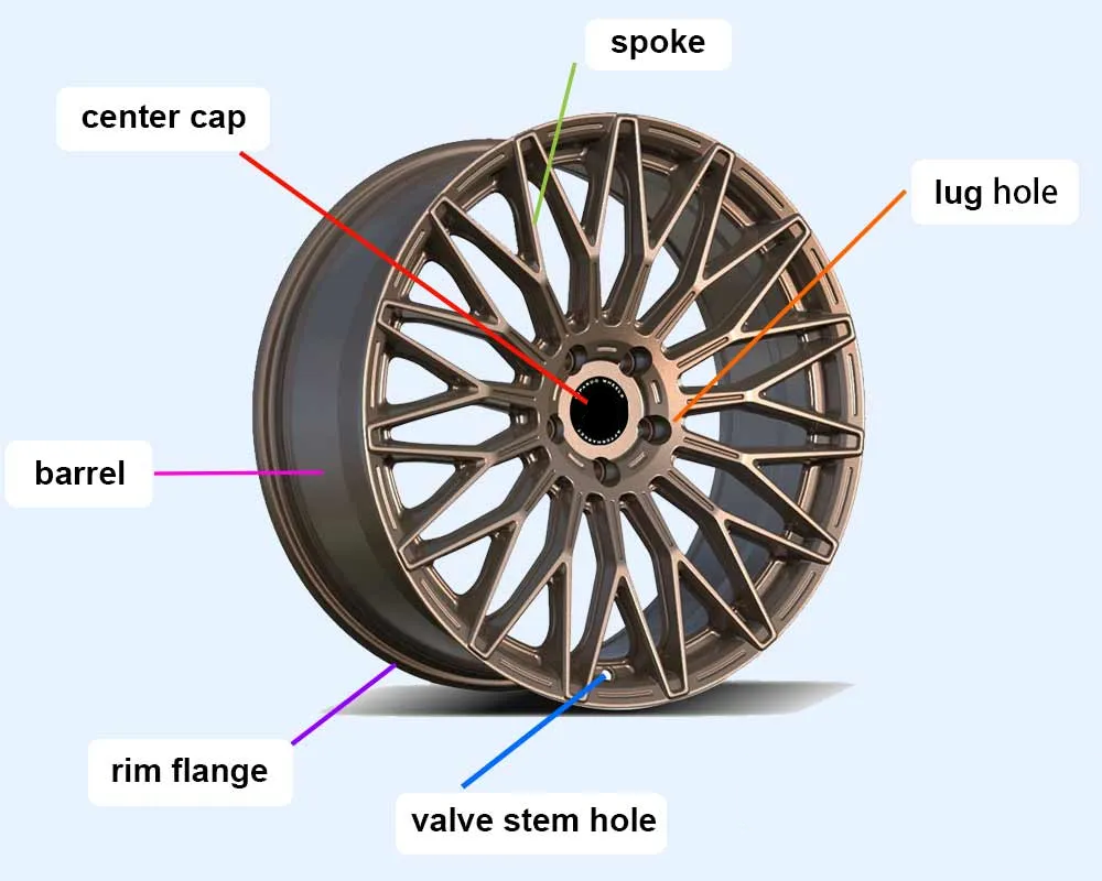
While a wheel may appear as a single integrated structure, its mechanical and industrial design comprises multiple precision-engineered zones. Below is a comprehensive breakdown of the core anatomical features of a wheel and their respective engineering functions.
1. Exterior and Face Components
1.1 Spokes
- Definition & Function: The structural beams radiating outward from the center plate to the outer rim barrel.
- Engineering Purpose:
- Load & Torque Transfer: Spokes support the vehicle’s vertical static load while uniformly dissipating the driving torque from the drivetrain and braking torque from the calipers across the outer barrel.
- Brake Cooling: At high rotational speeds, the pitch angles and cross-sectional contours of the spokes act as centrifugal impeller blades, rapidly drawing away heat generated by the brake rotors and calipers.
- Weight Reduction (Back-Pocketing / Side Milling): High-performance custom forged wheels often feature CNC pocketing along the sides and rear faces of the spokes. This strategy preserves the I-beam bending stiffness while removing non-load-bearing mass.
1.2 Center Bore & Center Cap
- Center Bore (CB): The precision-machined circular opening at the exact center of the wheel, designed to seat directly over the vehicle’s axle hub spigot.
- Hub-Centric: The bore diameter is machined to match the factory axle hub within a tight tolerance (typically H7), allowing the axle hub itself to support vertical shear stresses.
- Lug-Centric: Universal aftermarket wheels typically feature an oversized center bore (e.g., 73.1 mm), requiring hub-centric rings to eliminate potential high-speed wheel vibration.
- Center Cap: A protective and cosmetic cover that seals the axle spindle nut from dust and road grime. High-end custom forged wheels generally feature 6061-T6 billet aluminum CNC-machined caps fitted with rubber O-ring weather seals.
1.3 Lug Holes & Hub Mounting Surface
- Lug Holes (Bolt Holes): Precision holes arranged to receive mounting studs or wheel bolts. The circular pitch path traced through the centers of these holes defines the PCD (Pitch Circle Diameter).
- Lug Seat Profile:
- 60° Conical / Cone Seat: The standard specification for the majority of aftermarket wheels.
- Ball / Radius Seat (R-Seat): Standard OEM fitment for many European vehicles, including Audi, Volkswagen, and Porsche.
- Flat / Mag Seat: A flat-face design with integrated washers, frequently found on select OEM Toyota and Lexus wheels.
- Hub Mounting Pad: The flat, machined contact face on the rear of the wheel that mates flush against the brake rotor hat. Its surface flatness and perpendicularity tolerances directly govern radial runout and dynamic balance.
2. The Rim Barrel & Sealing Architecture
The rim barrel supports the tire and forms a hermetically sealed pressurized air chamber. Every contour across the barrel profile serves a vital structural and operational role.
2.1 Rim Flange
- Location: The raised, vertical retaining edge at the outermost perimeter of the wheel.
- Engineering Purpose: Prevents the tire bead from sliding off sideways when subjected to lateral g-forces during high-speed cornering or aggressive drifting.
- Profile Designations:
- The vast majority of passenger vehicles utilize the J-type profile (flange height approximately 17.5 mm).
- Select performance sports cars and SUVs feature the JJ-type profile (height approximately 18.5 mm).
- Steel wheels and vintage utility trucks commonly utilize the B-type profile.
2.2 Bead Seat
- Location: The horizontal ring surface situated immediately inboard of the rim flange, typically machined with a 5° taper.
- Engineering Purpose: Once inflated, internal tire pressure (2.2 to 3.0 bar) presses the tire bead tightly against the bead seat to establish an airtight seal.
- Knurled Bead Seats: On high-horsepower drag setups or tuned track cars, extreme instantaneous torque can cause the tire to slip circumferentially around the wheel. Knurled bead seats incorporate micro-textured grooves or laser-etched teeth along this seat to mechanically lock the tire in place.
2.3 Safety Hump
- Structural Form: A raised circumferential ridge located on the inboard edge of the bead seat (marked on engineering drawings as H or H2 for single or double humps).
- Safety Redundancy: If a vehicle hits a severe impact or experiences low tire pressure, the hump acts as a mechanical barrier, preventing the tire bead from dislodging into the drop center and causing a blowout.
2.4 Drop Center / Well
- Structural Form: The deep, recessed channel with the smallest diameter situated along the center section of the barrel.
- Mounting Principle: The outer flange diameter of a wheel is larger than the inner diameter of an unmounted tire. During mounting, the technician drops one side of the tire bead into this recessed well, creating the clearance required to lever the opposite bead over the outer flange without tearing the rubber bead core.
3. Structural Division of the Barrel (Inner vs. Outer Barrel)
The barrel is divided into two distinct structural zones, each subject to different mechanical demands:
| Component Name | Structural Location | Mechanical Characteristics & Engineering Demands |
| Outer Lip / Outer Barrel | The outward-facing, visible section extending from the center face to the front flange. | Defines the wheel’s cosmetic style (such as deep-dish or flat face profiles); withstands lateral support loads and is directly exposed to curb rash. |
| Inner Barrel | The inward section of the barrel extending toward the vehicle chassis and suspension. | Bears the highest dynamic bending stress across the wheel assembly. Because the inner edge lacks spoke support, it is the primary weak point for out-of-round deformation or cracking when striking potholes and road hazards. Flow-forming technology specifically stretches and compresses the metal grain structure here to counter these stresses. |
4. Engineering Terminology Quick Reference
| Engineering Term | Primary Function | QC & Fitment Focus |
| Wheel Face / Center Disc | The structural face of the wheel. | CNC profile tolerances, surface finish consistency, and baseline balance. |
| Spoke | Structural members joining the hub and rim. | FEA stress distribution, back-pocket depth, and brake caliper clearance (X-Factor). |
| Hub Mounting Surface | Rear contact pad mating to the rotor hat. | Surface flatness tolerance, lateral runout, and lug seat hardness. |
| Center Bore (CB) | Central axle registration bore. | Bore tolerance (typically H7), hub pilot concentricity. |
| Rim Flange | Outermost edge securing the tire bead. | Edge curvature smoothness, powder coat/clear coat thickness, and curb impact resistance. |
| Bead Seat | 5° tapered landing zone for the tire bead. | Airtight seal integrity, surface roughness, and profile angle accuracy. |
| Safety Hump (H2) | Dual circumferential retaining ridges. | Ridge profile height and transition radii to prevent bead unseating. |
| Drop Center / Well | Deep recessed center channel. | Minimum wall thickness verification and tire mounting clearance. |
| Valve Stem Hole | Machined orifice for the inflation valve. | Clean chamfering, burr removal, and clearance for OEM/aftermarket TPMS sensors. |
FREQUENTLY ASKED QUESTIONS
The outer barrel (lip) supports the exterior tire bead and primarily defines the wheel's aesthetic dish and lateral stiffness. In contrast, the inner barrel bears the highest dynamic bending stress from vehicle weight transfer and road impacts. Because the inner edge lacks direct support from the spokes, it is more susceptible to out-of-round deformation or cracking. High-performance wheels address this by using flow-formed or 6061-T6 forged construction, which aligns the grain structure to maximize rim barrel tensile strength.
Because a wheel’s outer flanges have a larger diameter than the inner diameter of an unmounted tire, a drop center (or well) is engineered into the barrel. It provides a recessed channel where the tire bead can drop, creating the slack needed to lever the opposite bead over the flange without damaging the tire bead. On the inner side, the profile of the drop center directly determines the clearance for oversized brake calipers and suspension links.
Hub-Centric wheels match the vehicle’s hub snout diameter with precise tolerances (typically H7), allowing the axle snout to bear vertical shear forces while lug nuts only clamp the wheel axially, eliminating vibration at high speeds.
Lug-Centric wheels feature a larger universal center bore (e.g., 73.1mm) and rely entirely on tapered lug studs for centering unless matched with hub-centric rings.
For custom forged wheels, we manufacture dedicated 1:1 hub-centric center bores for specific vehicles. For wholesale casting/flow-forming orders, universal center bores with matching aluminum hub rings are available upon request.
The lug seat distributes clamping force onto the wheel mounting pad. Mixing seat profiles causes severe localized stress concentration:
6061 Conical Seat: Industry aftermarket standard.
Ball/Radius Seat (R12/R13/R14): Typical for OEM European vehicles (Audi, VW, Porsche).
Flat/Mag Seat : Common in Toyota/Lexus OEM fitments.
Using ball bolts on a conical seat results in narrow line contact rather than full-surface mating, leading to hardware loosening, sheared lug studs, or cracked bolt holes under high torque.
The safety hump (designated as H2 for double hump) is an annular ridge inboard of the bead seat that prevents the tire bead from slipping into the drop well during hard cornering or low pressure.
For high-torque electric vehicles, tuned race cars, or drag applications, instantaneous torque can cause the tire to slip circumferentially along the smooth bead seat. Knurled Bead Seats add machined micro-teeth along the bead surface, mechanically locking the tire bead in place to eliminate tire slip, preserve dynamic wheel balance, and maximize power transfer.